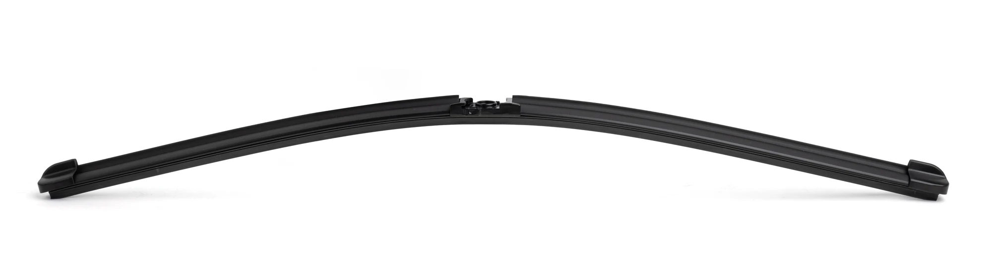
What Is a Wiper Connector? Structure and Sourcing Checks
Published by QINAI (瑞安市汽耐雨刷制造有限公司).
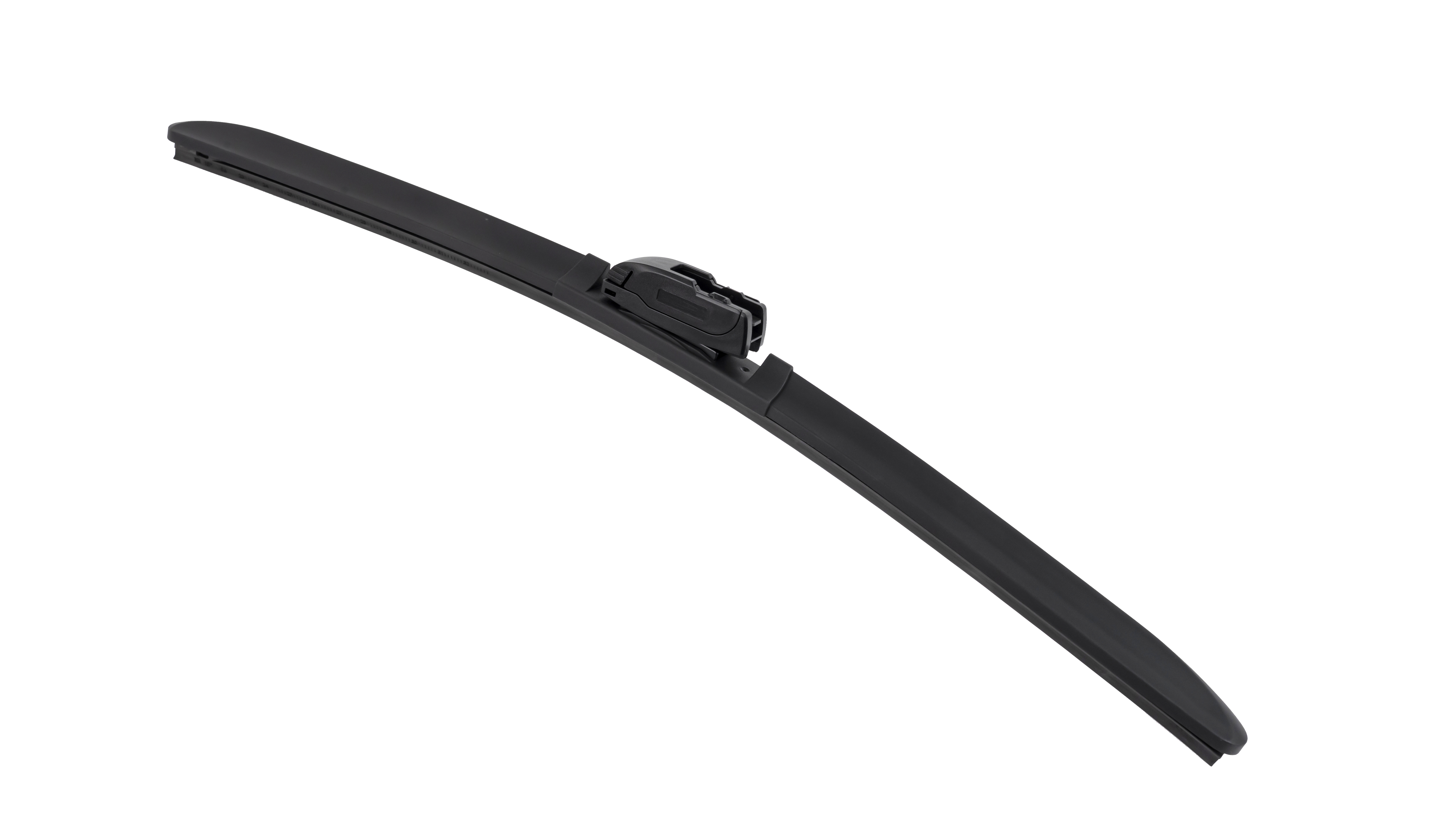
A wiper connector is part of the connection between a blade assembly and its mating arm structure. Depending on the design, a separate adapter may also be involved. Identify the complete combination before evaluating a loose connector by its outer shape.
Which connector features matter?
Locate the body-side attachment, arm-side opening, locating features and retention mechanism. Their arrangement determines where the parts meet and how the installed position is established. Some designs also require movement around a pivot; intended movement must be distinguished from disengagement.
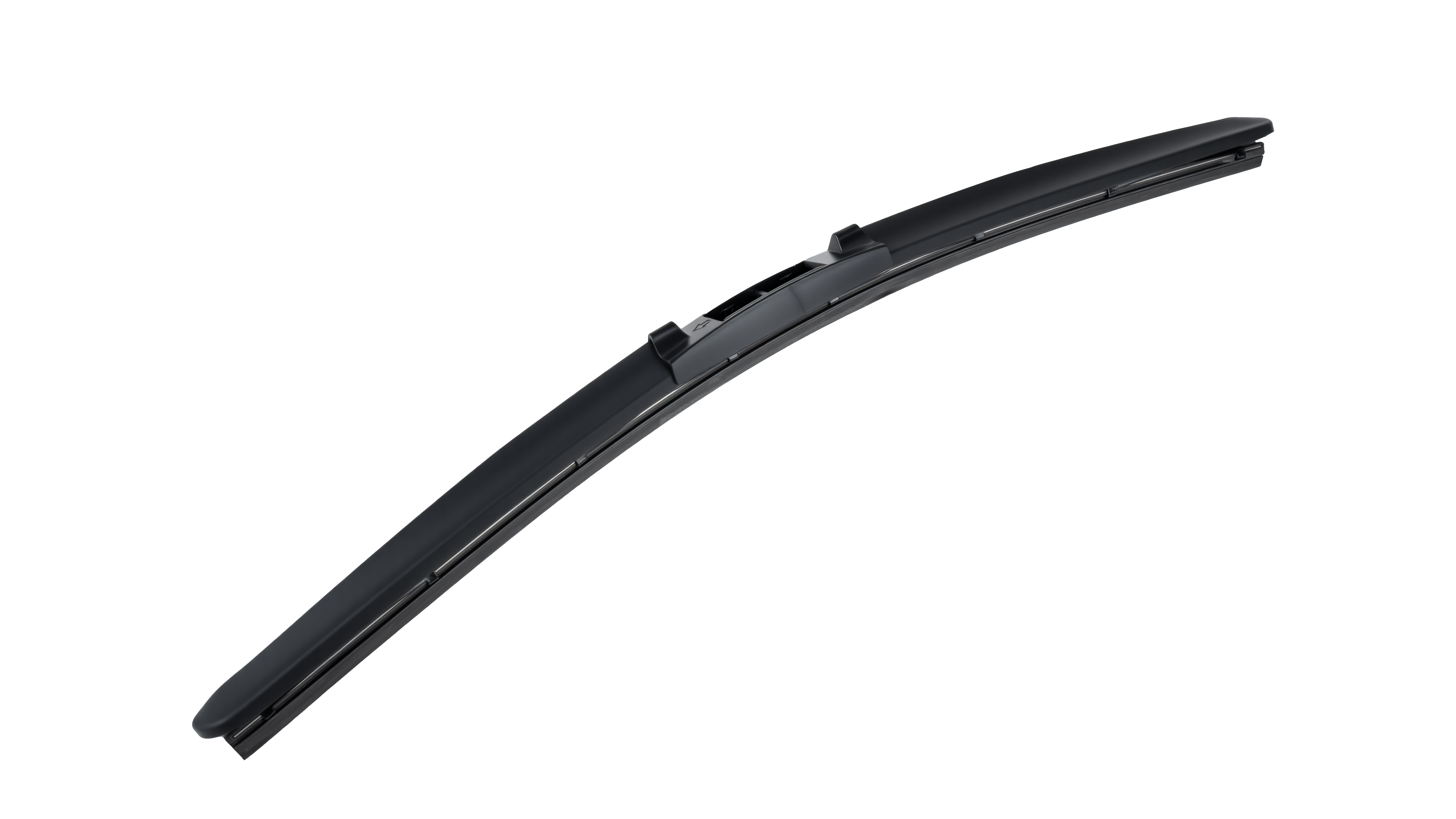
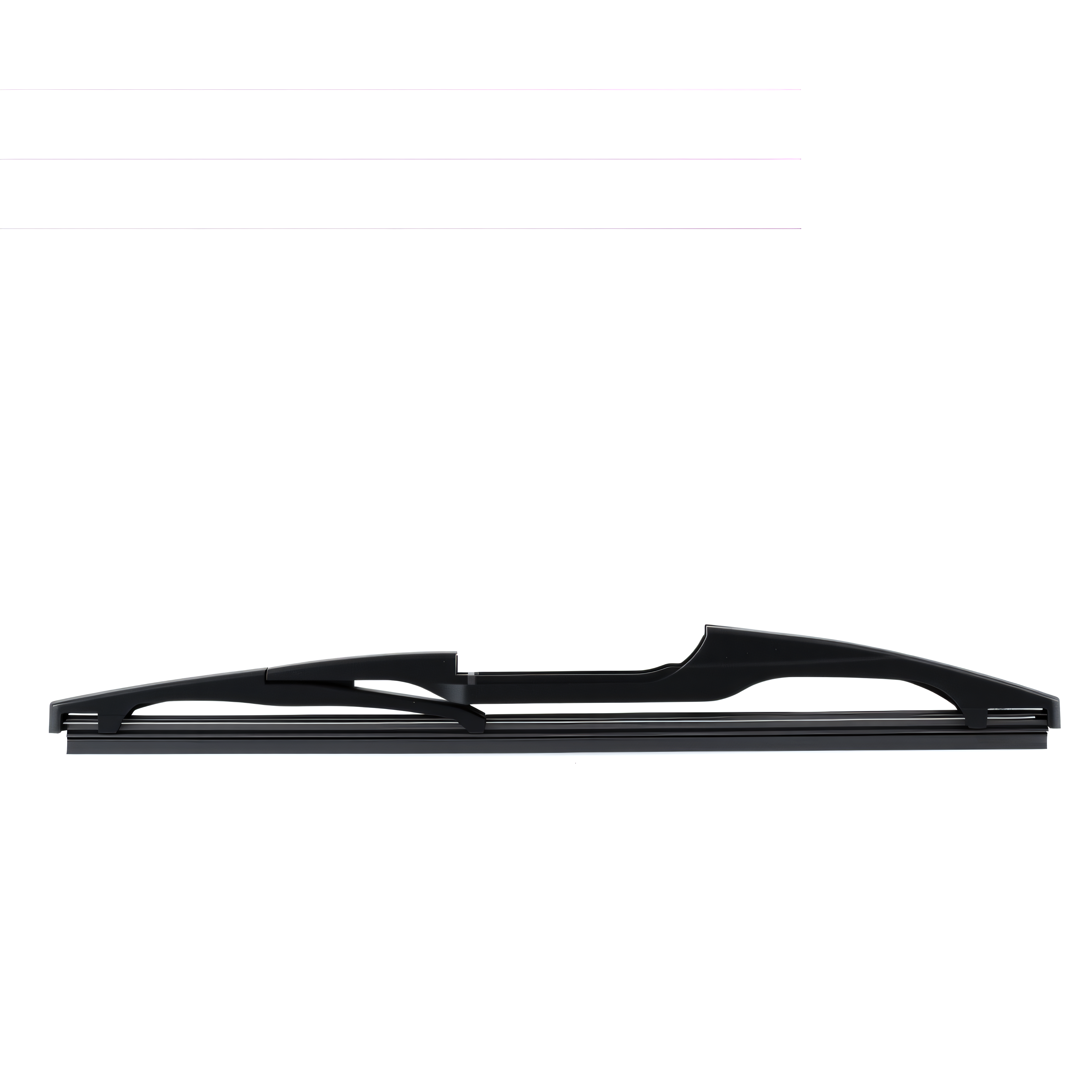
The existing H-S14A photograph is a catalogue reference. Use its product gallery to discuss visible features, with the actual mating part supplied for an assembly assessment.
| Feature | Useful review input |
|---|---|
| Entry opening | View of the matching arm end and insertion direction |
| Locator or stop | Detail showing the intended seated relationship |
| Latch or cover | Open and installed views, as applicable |
| Pivot and clearance | Relevant positions and surrounding boundaries |
Position, retention and movement are different tasks
A locating feature establishes where two parts sit relative to each other. A retaining feature limits separation in a particular direction. A pivot may allow movement that the assembly needs. These tasks can coexist in a compact connection, so the presence of movement does not, on its own, describe the state of the retention mechanism.
A simple hinged joint illustrates the distinction: two parts may rotate around an axis while another feature prevents them sliding apart along that axis. This is a general mechanical example, not a description of every QINAI connector. The actual permitted motion and separation constraints need to be identified on the specific combination.
Look beyond the outer cover
The visible cover can be useful for recognizing a component and operating its release. The surfaces that locate and retain the mating part may be underneath it. A closed cover is therefore only one observation. It should be connected to the intended position of the parts inside and the applicable installation check.
When a connection stops partway through insertion, identify the stage and touching surfaces before proposing a change. An obstruction at the entry opening differs from interference near the final position. Describing both as a tight latch can send the review toward the wrong feature.
Photograph both boundaries of the supplied part
A loose connector has more than one relationship to explain. Show the arm-side interface and the body-side attachment, together with an overall image that establishes their positions. If the part cannot be separated safely as instructed, show the visible state and identify the hidden area. Do not modify it merely to produce a clearer photograph.
Can one measurement identify the connector?
One width or height can narrow a search but cannot establish the complete match. Record dimensions from defined reference surfaces and compare the relevant mating features. A worn or damaged sample may not represent the intended geometry.
What should be checked after identification?
Review installation, retention, required movement and release with the intended parts and applicable instructions. Keep unresolved points in the sample record rather than treating a clipping sound as complete approval. Continue with the locking guide or the selection sequence for the next review.
FAQ
It is one observation, not a complete check. Compare the underlying parts with the intended installed position and perform the check specified for that design.
Identify the blade body and target arm end, including an adapter if the combination uses one. These establish the interfaces a loose connector photograph cannot show by itself.